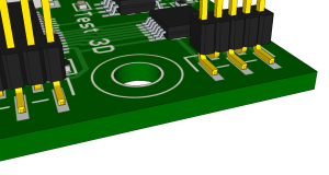
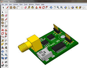
원본 링크 https://eagleup.wordpress.com/
Welcome to eagleUp
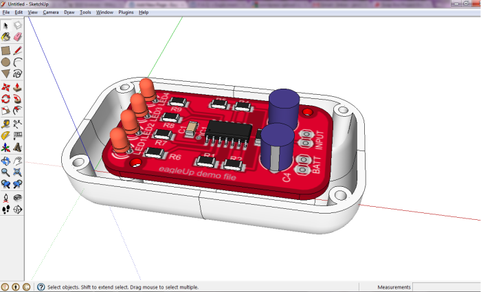
Welcome to eagleUp website. If this is your first visit please check the installation page with a complete step by step tutorial on the setup. Then you can follow atutorial on how to use eagleUp with the example provided.
For the model of your own project you will need some 3D parts. You can get them from the warehouse, or draw them yourself. It’s quick and simple. You can alsoimport step files for the mechanical parts.
Feel free to leave a feedback in the comments or by email.
eagleUp 4.5
With the introduction of Eagle 7.x it was time to refresh eagleUp.
First a few statistics. Since its initial release in 2010 eagleUp website had 500k page views and more than 30.000 downloads.
You can download eagleUp 4.5 on the installation page.
eagleUp 4.5 brings :
- compatibility with Eagle 7.x
- compatibility with Sketchup 2014
- PCB and parts are grouped and placed on different layers for easier manipulation
- faster import if you build the model a second time without exporting, by re-using the existing texture
- faster import by adding copies of multiple parts
- the EAGLEUP attribute can be used to ignore some parts : use any of the keywords NULL, N/A, DNE, DNI, DNP
eagleUp 4.5 uses the RBZ plugins of Sketchup. No more manual installation necessary! More details on the installation page.
Thanks Glenn for your ideas and code example. Thanks as well to all the users who reported issues and suggested features.
Please report any issue your encounter in the post comments.
eagleUp and Sketchup 2014
Sketchup 2014 changed the Ruby API that eagleUp uses, and the plugin management. I will publish shortly eagleUp 4.5 with a couple of new features, but in the meantime this is how you can make eagleUp work with Sketchup 2014 :
- location of the Plugins folder is C:\Users\[your user name here]\AppData\Roaming\SketchUp\SketchUp 2014\SketchUp\Plugins
- the folder might be hidden by your system
- on OS X the Plugins are located in /Users/[your user name here]/Library/Application Support/SketchUp 2014/SketchUp/Plugins
one line of the eagleUp_import.rb file needs to be modified on line 734 cmds.each do |line| becomes cmds.each_line do |line|- please download and use the import script modified for Sketchup 2014 at this link
- that’s it
I have checked with the demo PCB and all was working as usual. Please report if you have any issue with the new version of Sketchup.
edit : added modified importer for Sketchup 2014
eagleUp 4.4
Recently, many users have reported issues with the model lacking the tracks and silk images. The issue was caused by a change in the recent versions of ImageMagick. We have now fixed this issue thanks to Edwin, and took this opportunity to improve even more eagleUp.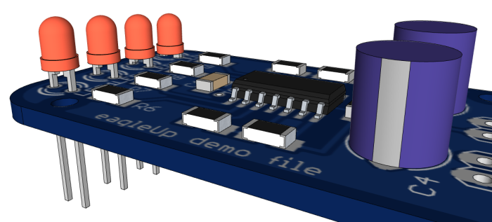
eagleUp 4.4 brings compatibility with ImageMagick 6.7.7 and Eagle 6.x. as well as with the previous versions.
Top and bottom textures are generated faster and will look better near holes.
Parts placement is more precise, with um resolution.
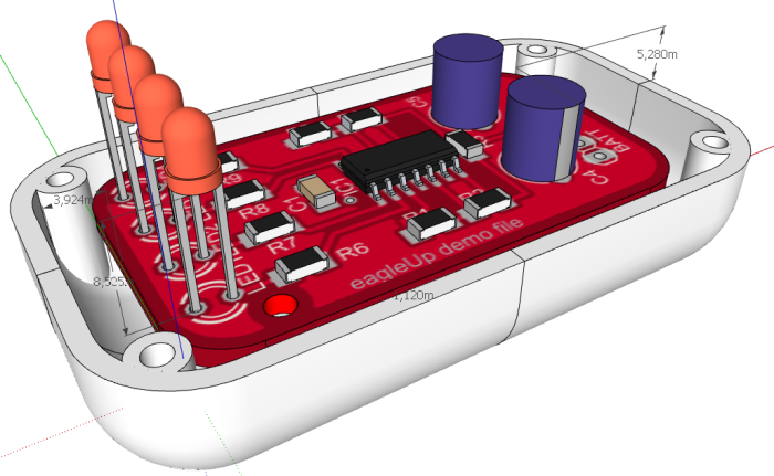
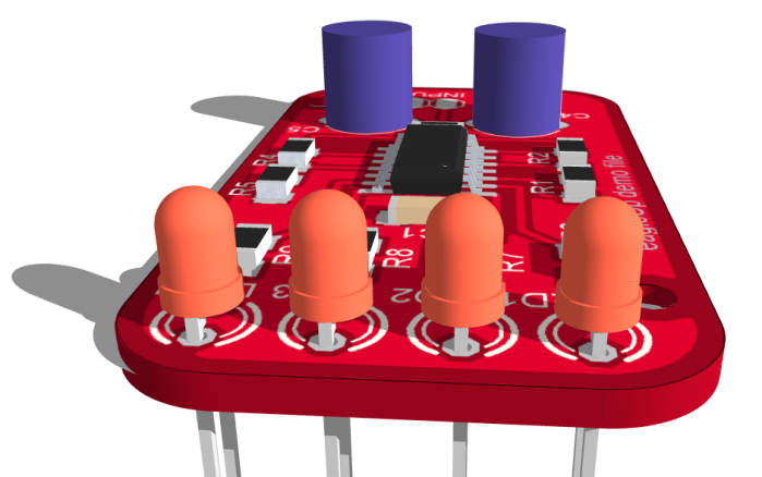
The EAGLEUP attribute gets a third parameter to modify Z-axis offset without modifying the 3D model. On the image above the Led have 0.5mm offsets. Syntax can include {part_name} {;{M}{Rxxx}} {;yyy.yy u}, where yyy.yy is the vertical offset (positive or negative float value) and u the unit. Unit can be mm, mil, mils, or inch. To move the part upward by 0.5 mm, add the attribute EAGLEUP with value ; ; 0.5 mm
The files are now handled with relative paths, so the eagleUp export folder can be moved around. This also helps with non-english characters, such as ö, ü, in the path (simply avoid them in the name of the export folder).
Two new options for the silk layers : none, and custom. In custom you can define your own mix of layers used for the silk. Type the layers separated with a space, for ex 21 25 51.
The new version of eagleUp can be downloaded here. Replace both the old ULP and RB files with the new ones.
SketchUp showcase
Google published recently a showcase page. What can you do with SketchUp, and how can it increase your efficiency.
We are happy to see that eagleUp is represented by the Akafuino X showcase. As you imagine, this show is about a circuit board design, using eagleUp to improve the board before production.
http://www.google.com/sketchup/showcase/project/akafuino-x/view
Karl from Akafugu is a contributor of eagleUp : beta testing, bringing ideas of new functionalities, and many parts of the warehouse. We are happy to see your project promoted.
Quick news : eagleUp will receive an update in June. Compatibility with Eagle 6.x, improved modelling… Feel free to join the beta users list.
Jerome
Introducing advanced rendering
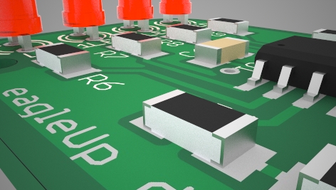
eagleUp helps designers fit their electronics into tighter enclosures by modelling accurately all the electrical and mechanical parts. The default rendering in Google Sketchup is practical and shows edges and guides, but this is not the best look to advertise your project. In this series of short articles we will demonstrate how to get stunning previews of your products, long before you get them in your hands.
Various realistic renderers exist on the market. We have set our choice on Maxwell for Google Sketchup. This renderer integrates well within Sketchup so you do not even need to open another application. All the modifications on your model have immediate effects. Rendering gets as simple as sketching.
Note : Maxwell renderer exists in multiple versions. Here we use the Sketchup plugin, in the free version. The main limitation is the max 800px wide images. This is sufficient to generate detailed previews of your project for web and presentation use. If you want higher resolution outputs you can purchase a cheap upgrade.
Download and install Maxwell for Google Sketchup (the free version is sufficient to evaluate and practice with photo-realistic rendering). Follow the instructions in thereadme.txt file (copy a folder and run an installer). The interface with the renderer can be found in a new toolbar or in the Plugins menu of Sketchup.
Note: due to uncompatibility between the latest Silverlight and Sketchup it is necessary to install Silverlight 4, and not the newer version 5. You can download it here.
Pre-requirement
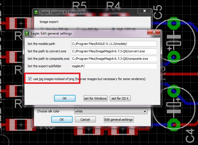
Maxwell renderer does not support the PNG images generated by eagleUp. In the general settings of eagleUp 4.3 you need to select the use jpg images instead of png. Then export and import again your project. You can leave this setting on.
Launching Maxwell Renderer
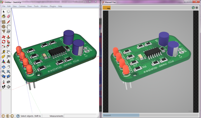
Load or import eagleUp demo project. Then click on the Fire button in the toolbar. This brings a new window that contains your rendered image. The size of the window determines the output image resolution, it is therefore easier to work on a dual screen workstation.
In Maxwell window click on the yellow Fire button. This launches the rendering. You can stop it at any time by pressing the Stop button. Photo-realistic rendering is a slow process that consumes a lot of resources. Maxwell renderer builds the image globally by increasing the detail level. At first you see a bunch of pixels, then your circuit take shape. Little by little, details appear, shadows, reflections and realistic textures. After a few minutes you should see this :
Maxwell renders exactly your Sketchup view. Rotate and zoom until you find the perfect point of view. The rendering is updated as you move around for real time feedback. You do not need to hide edges and other drawing marks. It is convenient to use the 1000:1 scale to get a fully focused image. If you work at scale 1:1 feel free to use the Plugins / Scale / Scale up 1000.
Improving the model
The model looks better but this is only the beginning. Open the scene manager (from toolbar or Plugins menu). You can adjust the lighting and materials of the scene. All your changes are updated directly so you can try all the settings.
Photo-realistic rendering is an art, and you will get the best of your models by trying different materials and parameters. Pick the material selection tool. Click in Sketchup window on your parts. You can see the material in use (silver, charcoal, …) and their properties. They are by default in automatic type. You can change to plastic or metal depending on the surfaces.
Each material can be customized to look as real as possible. Increasing the roughness will for example reduce the reflections. In the scene manager you can edit more properties for the material like textures and bump mapping. Maxwell renderer gives you free access to thousands of complex materials ready to apply. Check the material gallery and use the search engine to narrow the selection. You can download the materials and apply them with the MXM tab.
This first article is a quick introduction to photo-realistic rendering for eagleUp. Now it’s time for you to try it by yourself on your own projects and experiment with materials and textures. Feel free to share your best results in the comments ! We will open a dedicated section on the website with galleries and more tutorials.
Attribute and units
This post describes in video two new features of eagleUp 4.3 : the use of an attribute to specify the model for a component, and how to scale up/down and change the unit in your model.
eagleUp 4.3 introduces an attribute to link various skp models to a single Eagle footprint.
The default method to import the model of the part on the PCB is to look for a skp file that has the same name as the component package in Eagle. If my resistor R32 is based on the package R0805, eagleUp will look in your /models folder for a R0805.skp file. It can be located anywhere in the /models folder, in my case I saved it in /models/passive/resistors/SMD/
This method works well but sometimes you share a footprint between various component that are physically different. In my case I have a single 0805 package for all my passives: resistors, capacitors, inductors… Or you can have male and female connectors sharing the same footprint.
To differentiate them, you can now use an EAGLEUP attribute on your components. This attribute can be defined within the library (it then applies to all your components) or on board level for a single part. This flexible approach should work for every workflow. The new attribute feature only works in Eagle 5.x and newer.
The attribute value specifies the model name to use. If necessary you can also make some alteration on the model : change side and rotate. This is particularly useful for connectors that can be flipped in many orientations. The full syntax of the value is {part_name}{;{M}Rxxx}
eagleUp resizes your model
With eagleUp 4.3 the Plugins menu now has new feature to help resizing your models. By default eagleUp works in a 1000:1 scale that helps designing small features. As soon as your model is ready you can easily scale it down to the natural 1:1 scale if you prefer it. For imperial units users, you can also display the measurements in inches.
The initial 4.3 release had a minor bug that made the resizing wrong. This has now been corrected. If your scaling is wrong (scale by 10 was 100, and scale by 1,000 was 10,000) you can simply download the installation files again and replace the eagleUp_import.rb file, or correct the wrong line by yourself. The error was at line 808, you should replace “for iter in 0..iterations” by “for iter in 1..iterations”.
eagleUp 4.3
After more than 3000 downloads, it’s time to improve eagleUp and add to new features.
- fixed curved board outlines (see below the note on outline curves)
- eagleUp now supports 1:1 scaling as well
- eagleUp also includes functions for scaling and measuring the final circuit
- automatic resizing of models during import, you can mix scale indifferently 1:1 and 1000:1 objects
- add support for sub folder ! keep your work folder clean, all eup, png, log files can be placed in a user defined sub folder. Check the settings window.
- add an option for simplified vias (no drill) for faster import of large models.
- add a board thickness unit selection, you can enter 1.6mm as well as 60 mils
- add a log file of the missing parts during the import in Sketchup, the log file is saved next to the eup file
- add support for an attribute-defined part name (see below)
- add possibility of minor modifications of the part (rotation, board side) directly from the Board
- added option to create top and bottom images as jpg files (necessary for some renderers, do not use otherwise)
- Eagle installation < 5.9 (including 4.xx) should use a simplified legacy exporteravailable here. It keeps most of the features of the full version.
- new PCB colors available, like a white solder mask (Winter is coming !)

You can download eagleUp 4.3 here. Check out the installation and tutorial pages.
I would like to thank Karl for the Mac OS code and tests, and all the feedback from the beta version users.
Note 1 : Curved outline failing
This release of eagleUp fixes some issues with curved outlines. However some particular arcs still fail when the system uses comma as a decimal separator. The issue comes from Sketchup not behaving similarly on dot/comma systems. There is currently no fix for this known issue.
As a work around, if you meet the trouble of curved outline not closing properly in Sketchup, temporarily change your regional settings to use a dot. Then run the Sketchup plugin, save the model and restore your regional settings.
Note 2 : scaling 1:1
Users have often requested a way to model directly at scale 1:1 (in mm, in mils…). This is now possible but please keep in mind that Sketchup does not handle properly small details. You will quickly notice that arcs (for ex: curves pins of ICs) are impossible to model at this scale.
The reason is that Sketchup was originally intented for architecture modeling, not for the model of a 0402 resistor. Even with the template set to mm, the smallest dimension you can draw is about 30um and that this is too large for most arcs.
If you want to model at scale 1:1, I recommend :
– continue using 1000:1 models, and a template set to meters
– when your board is finished, use the Plugins/Scale/Scale Down 1000 function to resize it
– you can change the display units (mm, inch, mils) quickly with Plugins/Scale/Set units
Note 3 : components attribut
During the import step, eagleUp searches by default a part with the name of the component package (for exemple a resistor in 1206 package gets a part 1206.skp).
Now the user has the possibility to use a different part name at library and board levels. This makes the part management much easier.
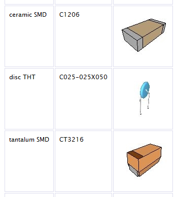
You can specify the attribute in the library, for exemple to make sure that all 1206 resistors will be modeled by R1206.skp, all 1206 capacitors by C1206.skp…
You can use this new feature to differentiate easily male and female headers, or right angled headers, that all share a common footprint.
You can also set or modify this attribute on the board as well : select the attribute tool, click on the component and add/edit the attribute.
The attribute EAGLEUP can have two parts, separated by a semi-colon ;
The first part defines the name of the skp file to use. The second part can be used to alter a part easily. For exemple a right-angled pinhead can be rotated, or placed on the opposite side.
The side and angle are defined the same way as for the other Eagle commands : MR90 codes for Mirror + 90 degrees rotation. R180 codes for a 180 degrees rotation…
The complete syntax for the attribute is : name = EAGLEUP, value = {part_name}{;{M}Rxxx}
Videos to illustrate the new features will be added soon.
Jerome
Warehouse update
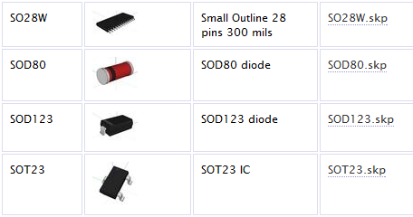
After a long period without updates, the warehouse of parts for eagleUp just got refreshed. The parts are now sorted by categories that you can download separately.
There are now parts for everyone, from the smallest SMD to the largest DIP packages.
These parts will help you start the 3D model of your own circuit. If you miss something, check the video tutorials on part modeling and import from stp/iges files.
You can send me your own models by email. I will upload them in the warehouse after a quick check. Remember to name them correctly or to write the exact part number.
Simpler STEP and IGES file import
The import has been simplified and uses MeshLab instead of Blender. Lighter software and faster conversion !
The process is not obvious and requires 3 applications so I made a short video tutorial to show how it works.
Feel free to comment on the process and on the video.
Jerome
Video tutorials
Today are introduced video tutorials.
They follow the text tutorials and make, I hope, the steps easier. You can find them on top of the installation, tutorial and modeling pages.
These are the first videos, so feel free to comment on the content and tools.
Jerome
edit: added the modeling videos
development ideas
eagleUp 4.3 is in beta test at the moment and will be released soon. It will fix some rounding errors for the edges that can appear if you have a very curvy board outline.
What do you want to see in eagleUp ? Here is a short list of what the users have requested so far :
- work in millimeters instead of meters. This request appears very often, but Sketchup is designed for buildings so it limits the precision at our low scale. But mm-scaling should be possible and will probably appear very soon in eagleUp.
- smarter part management. At the moment the name of the part.skp has to match the package name in Eagle so it limits strongly the flexibility. With the next releases the part will be handled differently and will allow the designer to change on the fly the parts, and why not pick directly from the eagleUp warehouse.
- multi-layer board 3D view. We have now achieved a nice and realistic preview of the parts and of the outside of the board, but when you work with multi-layer boards, it could be interesting to see the inside of the board : how the layers are connected, where is this via going, what is the separation between critical signals in the real board…
eagleUp made my day
In this post I publish some user comments that tell how eagleUp could help by saving time and money.
Take vertical measurements
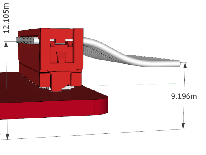
Measuring in the PCB plane is simple, but when it comes to vertical dimensions, the designer often has to read datasheets and to make estimation for the missing dimensions. With eagleUp, you simply assemble the parts as you would do with the prototype, and then take measurements with a virtual ruler. Quick and accurate !
In the example below, Joe needed to know the height of spacer necessary for the mounting of the PCB on the enclosure floor, and the total height. He used the import procedure to get an accurate model of the male and female parts of the wire to board connector. The result appeared immediatly.
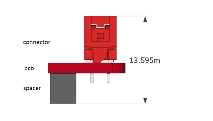 Then he needed to determine the path of the ribbon cable. The position of the ribbon was not indicated in the datasheet of the connectors, so he added a virtual ribbon cable, and could shape it to match the future location of the cables in the enclosure.
Detect collision in time
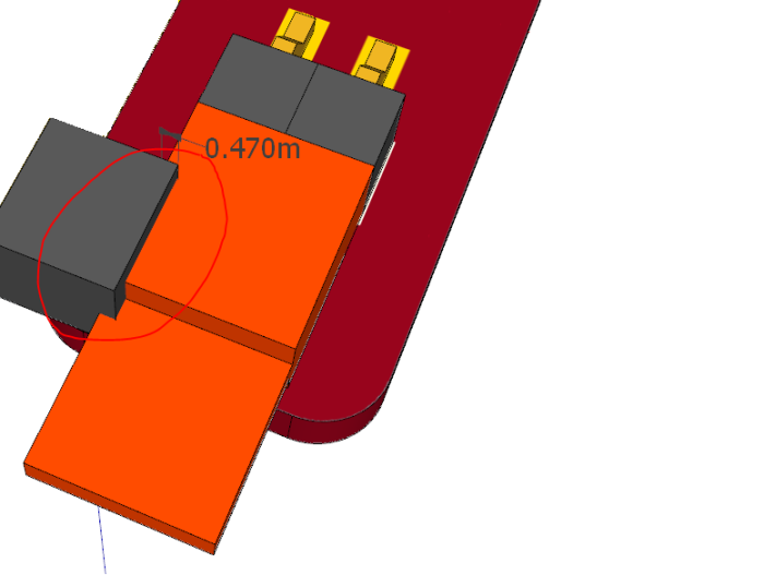
Before launching the circuit into production, Joe had a last look at the model, and saw something wrong. There was a collision between a spacer and a jumper. The jumper was added quickly at the end of the project and appeared fitting on the Eagle design. The mistake came from the spacer that did not appear in Eagle, as previously it was a completely empty area.
The mistake was detected on time and corrected, and the schedule was kept.
(Feel free to share your experiences in the comments or by email)
eagleUp 4.2
After a few days of beta testing, eagleUp 4.2 is now released.
This version focuses on reducing the amount of settings and on the automatic detection of the configuration. eagleUp is becoming more user friendly, thanks to your comments and suggestions.
The main new feature is that you do not need to manually edit the RB file for the settings any more. The paths and the settings for the board (colors, thickness…) are saved and restored at each launch.
You now have access to custom colors and can sort your SKP parts in as many sub folders as you want.
You can find eagleUp 4.2 in the installation page. Remember to check the tutorial as well.
Release notes :
- fixed an issue with decimal separator in the folder names.
- fixed an issue with comma as decimal sign and Windows XP platform.
- added decimal sign detection in Sketchup, no more errors due to a wrong setting (currently the first cause of troubles).
- added unit detection in Sketchup, warns the user and stop if meters are not set in the template (the second).
- added a custom color choice for easier users experiments with board colors, select the color ‘custom’, a popup will help you fill the values.
- added storage of users settings in eaglerc configuration file for Eagle versions 5.10 and above. All settings and preferences are now saved and restored at each launch for higher productivity.
- added storage of users settings in a text file for older versions of Eagle (equivalent to the previous line, but not as reliable in shared environment).
- added settings for the paths and commands (previously these values had to be edited by hand). At first launch the user can edit the paths (or choose the default values for Windows or for OS X). These settings can be accessed later in the eagleUp main window.
- added compatibility with multiple projects in a same folder by naming the exported images with the board name.
- added an option to export and import a design without the realistic PCB images. The image creation is a slow step, in particular for large designs. With this option you can make a quick preview, check for the missing parts, and when all is ready make the real export/import with the images.
- added an automatic correction of package names having a comma (replaced by a dot) or slash (/, replaced by _ ). SKP files should be named the same way.
- added support for sub folders in /models. You can sort your models as you want with as many levels as you need.
- added automatic zoom to the extent of the model in Sketchup.
The next version will have a better skp part management, and more error detection on the board level. Feel free to suggest any improvement you would like to see.
I am looking for a way to get photo realistic views of the assembled boards. If you are experienced with Blender or other freely available rendering software, please get in touch with me.
Jerome
import step files for your models
Many mechanical parts like connectors, switches and large parts are offered as STEP models by their manufacturers. Unfortunately there is no direct way to import them into Sketchup, so we usually have to redraw them from scratch based on the datasheet and some imagination.
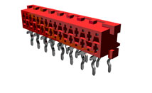
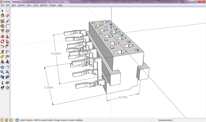
Lorenz wrote me a short description of his method to import STEP files. I will illustrate it with a Micro-Match connector, manufactured by Tyco. The reference of the part is 1-215460-0. Follow the link and download the STEP model (you do not need to sign in, just close the popup).
Locate the zip file on your computer and extract it. There should be a .stp file inside.
Download and install FreeCAD. This tool is multi platform. Launch it.
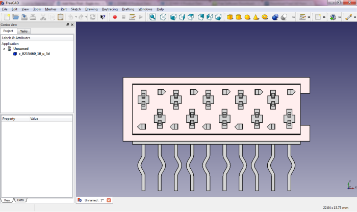
Import the model with File / Import .
Press ‘0’ (zero) for isometric view. Pretty realistic. It would be a lot of work to draw so many details !
Create a mesh for this model : Meshes / Create mesh from shape. Click OK in the left hand side tab.
Then click on “c_0215460_10_u_3d (Meshed)” and Meshes / Export mesh… Save as binary STL.
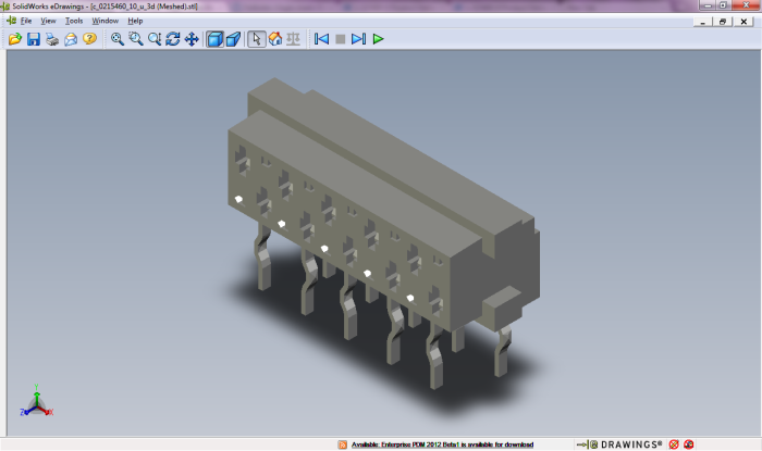
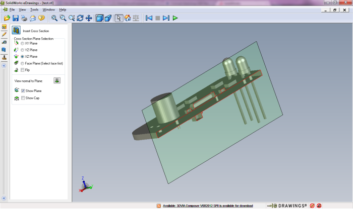
You can open the STL file with eDrawings to check the intermediate file.
Still looking nice ?
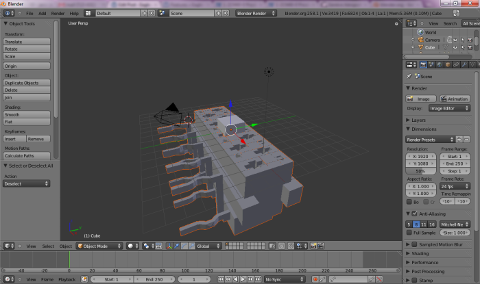
Now download and install Blender. This tool is multi platform. Launch it and import the STL file : File / Import / Stl…
Export as Collada (DAE).
Then Import the dae file in Sketchup. You can explode the model and edit it : add colors, re-orientate it.
A good check is to measure the component and check that the dimensions are correct (remember the scale : millimetres are now meters).
Summary : STP => STL => DAE => SKP
Feel free to share your own methods in the comments.
export your model as DXF or STL
Sketchup is a nice CAD tool but the SKP format is not the most useful. You cannot open it with many other software or share it with mechanical designers. Today we will see how to export it nicely.
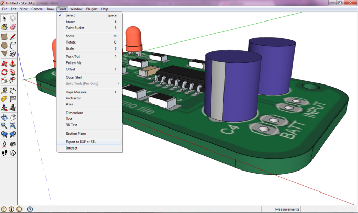
Following this link you can find a plugin for Sketchup that can write DXF and STLfiles. Copy the RB file in your Sketchup plugins directory. This plugin works for Windows and OS X.
Then open your existing design, or run eagleUp from scratch. You can find the export plugin in the tools menu :
Choose to export the whole model, then select an export in millimeters.
Finally you can choose your export format.
- the polyface mesh can help measurements on 2D drawings
- the STL gives a more useful 3D model
STL is widely used for milling, printing, and other quick prototyping.
There are several free viewers available. I can recommend eDrawings. Feel free toshare your experience in exports and 3D file formats in the comments.
Tomorrow in another post we will see how to import parts in Sketchup.
Beta testing
Do you like eagleUp and would like to contribute simply ?
Send me an email to register as beta-tester (write ‘beta testing’ in the subject).
You will receive the updates a couple of days before the public release.
Your task will be to try the new version on your computer and report any issue on the demo model and on your own models.
Windows, Mac and Linux users are welcome ! Users with non conventional settings as well.
Thanks,
Jerome
PS: version 4.2 is in the pipeline with a couple of interesting new features…
the warehouse is open
The part warehouse is now open.
All the parts you find on this page have been tested with Eagle default footprints in size and orientation. You can use them safely in eagleUp.
You can send your own parts by email, with the name of the package, or enclosure, or hardware, you have drawn.
eagleUp 4.1
The version 4.1 corrects a couple of minor issues found in eagleUp 4.0 and introduces an automatic warning when a newer version is released.
Release notes:
- added automatic check for latest version
- added compatibility with outline lines placed on package level
- added option to export only the board to Sketchup (no parts placed on the PCB)
- corrected non-plated hole color
You can download eagleUp 4.1.zip and replace the ULP and the RB files.
For Mac users, check Tom’s comment on OS X settings.
Remember that a parts warehouse is coming soon. Please send your best creations !
parts warehouse in preparation
The most wanted feature for eagleUp last year in your comments and emails has been the parts warehouse. It seems that everybody likes community contribution. I plan to open the warehouse soon, so please send me by email :
- the part you have drawn in skp format, scaled 1:1000 as usual
- the exact name of the package (SO08-150 for an IC, 6032-28 for a Tantal cap…)
- the name used in the default Eagle library (SO08 and CPOL-EUCT6032 respectively)
- a link to a datasheet of the package if necessary
- the author name you’d like to see appear
new version released
Dear eagleUp users,
version 4 has been released. Most of the import and export procedures have been automatized to simplify the process, so that you can focus in design, and not in the conversion 2D/3D.
With the version 4, you export from Eagle in 2 clicks, and import into sketchup in 3 clicks. No more tiring image creation and manual import necessary. Give it a try !
You can check the installation notes. You will find there the download of version 4.0
Then have a look at the tutorial. It only takes a few minutes to complete and shows the new features of eagleUp.
Thanks to Erik, this version should be Mac friendly. Please comment on any issue you find on your way.
Model your own parts
Interested in Eagle’up but you don’t know how to model your favorite components ?
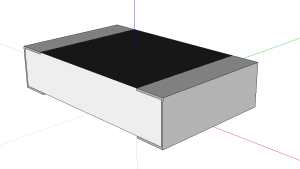
I wrote a tutorial to help you. It starts with a simple 0805 resistor and shows you the spirit of the modeling. How to model it, and how to model it well and quickly.
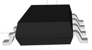
When you are familiar with the resistor modeling, check how to model an integrated circuit. It is just a bit more complicated, but with the tutorial you can do it in less than 5 minutes !
After that, you will have all the tools to draw your own parts.
Eagle’up brings colors to your 3D model
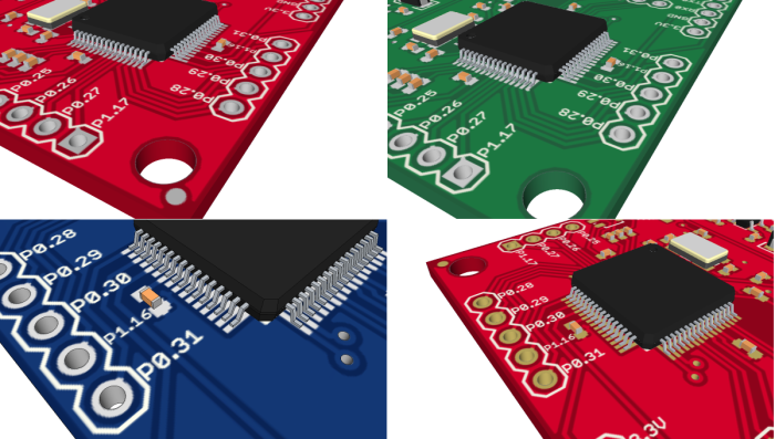
As promised, the version 3 of Eagle’up gives you the choice of colors for your board. Currently you can pick a green, blue or red solder mask, and silver or gold plating for your drills. These are the most common selections from the PCB manufacturers.
You can of course add your own colors, or adjust the tone of the ones provided, check the scripts for more details.
I will soon publish a page with all the technical details and process used in Eagle’3D.
The drills larger than 2mm are not plated by default, usually they are mounting holes.
The User Interface has been improved so that you only see one popup per missing package. The Ruby script warns you if you have multiple drills superposed, and only keeps one so it should not affect the model.
You can download directly the new archives here:
EagleUp tools 3.zip (save as … then rename as .zip)
You just need to replace Eagle_up_export.ulp , eagle_import.rb and the batch files. Obviously you run only the batch file with the color scheme you desire. The process to go from Eagle board to SketchUp model is the same as before.
Please report any issue with this new version.
coming soon
- colors, personally I am fond of red boards. A selection of colors are on their way for even more realistic previews.
- plated holes, small detail but important visual effect
- improved drilling and UI
Eagle’up drills for you
Finally it was not so difficult. The updated Eagle’up now drills all the holes of your PCB to create an even more realistic view of your board. This will also help with 3D assembly of boards.
The screenshots and tutorial have been updated. Drilling with SketchUp was not a simple task, but the result looks great.
Eagle’up goes public
After a few tests, Eagle’up is ready for the first release.
Eagle’up is a small tool I have developed to help you model your electronic design in 3D. This can be very useful for the integration, or to get a nice looking preview of your project.
All the resources are free so you can try it without constraints.
You can start by discovering how Eagle’up can help you, and have a look at its main features. If you like it, give it a try following this tutorial, I provide you all the necessary files.
You can leave your feedback in the comments, or by email.
Jerome
PS: I have received comments about disturbing snap popups appearing over the images on this blog. They can be disabled, check the menu on top right corner, or you can use Adblock.
'pcb > eagle' 카테고리의 다른 글
| 3D 내보내기 [3D Export] (0) | 2015.04.20 |
|---|
